|
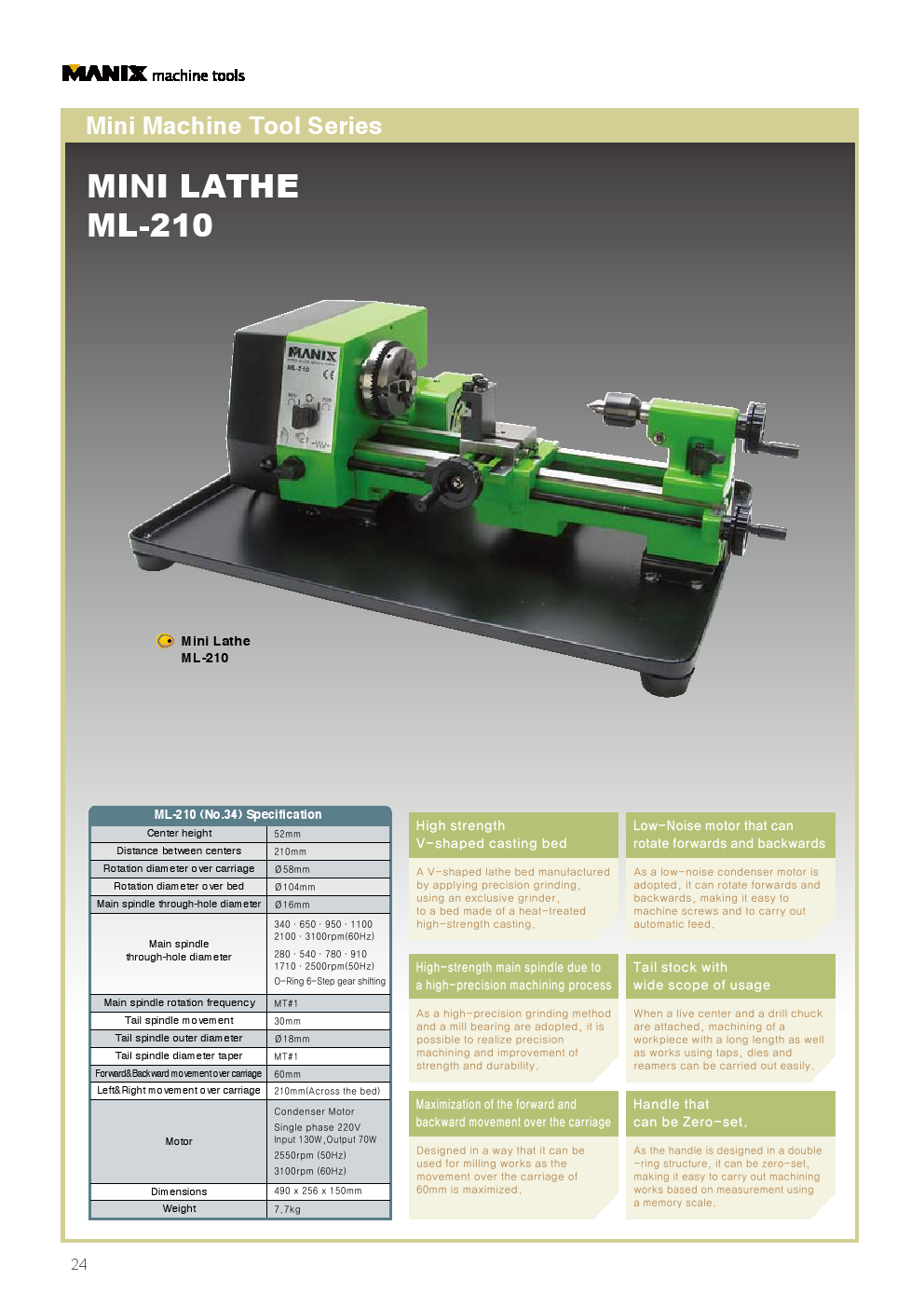
MINI LATHE ML-210
DO IT YOURSELF MACHINISTS AND PROFESSIONALS ENGAGES IN PRECISE MACHINING
Manix Mini Lathe ML-210 is a high performance miniature lathe developed on the basis of long experience and precise machining techniques.
Though compact in size and light in weight, ML-210 presents the capability expected in standard large lathes. Due to the well-designed structure with selected material, not to speak of high performance and accuracy, excellent rigidity and durability are also secured. In addition, the comprehensive range of accessories produces remarkable versatility.
Manix Mini Lathe ML-210 is recommended to Do-It-Yourself machinists and professionals engages in precise machining.
ML-210
1. EXTREMELY RIGID HARDENED AND GROUND BED WITH VEE WAYS FINISHED TO A HIGH ACCURACY.
- The box section with well located cross bracing and Vee ways makes it superbly rigid and distortion free.
2. REMARKABLE CONDENSER MOTOR WITH QUITE OPERATION
- The change between forward and reverse is achieved simply by switching, which makes threading and automatic feeds very convenient.
3. MAIN SPINDLE FOR PRECISE MACHINING
- The accurate and hardened Main Spindle is supported by two ball bearing races. Thus, long lasting accuracy is secured.
4. VERSATILE TAIL STOCK
- With Dead or Live center fitted, turning a long workpiece is easily performed. Drilling, reaming and so on are also practicable with drill chuck.
5. CARRIAGE OF GENEROUS TRAVEL
- A generous 60 mm cross feed movement ensured a sufficient range for both lathe work and milling.
6. CONVENIENT 0 (ZERO) – SETTING
- Feed handles are of coaxial ring construction which permits 0-setting operation. Cutting margin is read directly without the need of calculations.
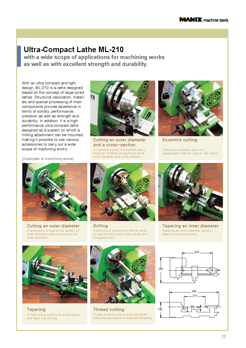
1. Cylindrical turning & counter facing: Turning on step, using 3-jaw universal chuck with jaws reversed to clamp workpiece of large diameter 50mm.
2. Eccentric turning: Making eccentric boss out of square workpiece clamped with 4-jaw independent chuck.
3. Turning between centers: Grooving on workpiece held between centers with Face Plate, Lathe dog and centers.
4. Drilling: Drilling on hexagonal bar with Drill chuck.
5. Boring: Boring taper hole with Boring bit fitted to Taper turning attachment.
6. Taper turning: Turning on the end of workpiece with taper turning attachment, where workpiece is held with Steady rest.
7. Threading: Threading on square workpiece clamped with 4-jaw independent chuck.

1. Wipe the main spindle and 3-jaw chuck with dry clothe before attaching.

2. Fix the 3-jaw chuck tightly by the hexagon bolt.

3. Turn the tail stock handle and pull out the #1 tail spindle about 5 mm to the arrow direction as shown in the picture.

4. Fix the #1 Dead center(No.3505) on the tail spindle to the arrow direction as shown in the picture. Try to feel like hammering in instead of pushing in.

5. When it’s attached like shown in the picture, try to pull out dead center by hand to see if it’s steadily fixed. Turn the handle to the opposite direction and insert the tail spindle completely, dead center automatically comes out.

6. Turn the handle to relocate the tail stock to arrow directions. You must turn the handle to tighten the tail stock after relocating.

7. Unfasten the bolt by the wrench included in the bit holder.

8. Attach the insert tip as shown in the picture.

9. Put the #1 right height of a metal piece on the tool post as shown in the picture.

10. Put the bit on top of it, move the tail stock near the tool post and check if the dead center’s end has same high as the end of insert tip. Use different thicknesses of metal pieces to adjust the height of dead center’s end and the end of insert tip most accurately, and fasten it with #1 bolt.
“The center of the tail spindle is manufactured to be accurately same height as the center of carriage on the lathe. Above process is to adjust the height of insert tip and the end of the dead center for the best operating results.”

1. You can use the #1 Chuck handle to open and close the #2 jaw of 3-jaw chuck. Insert the material tightly in the 3-jaw chuck.

2. Try to move the material by hand to check if it is tightly fastened. If it is loose, try to fasten it again to avoid falling out during process.

3. When you separate the jaws from 3-jaw chuck, you can see the numbers on them as in the picture. You can use a set of jaws by correct way (max. 13mm) and reverse way (max. 49mm).

4. Turn the #1 handle to move the tool post vertically (to Y axis). The smallest gradation is 0.025mm. So if you turn 4 small gradations (one big gradation), it will move 0.1mm vertically.

5. Turn the #2 handle to move the carriage horizontally (to X axis). The smallest gradation is 0.025mm as well.

6. Turn the #1 power switch to the arrow direction to turn the main spindle. Use the X axis handle and Y axis handle for the cutting process.

7. Adjust the bit’s travel speed and cutting amount according to the material’s type and size. If you try to cut too much amount at once, the machine would be easily overloaded and bit would be easily worn out.

8. If you unfasten the #1 cover bolt, you can open the cover like shown in the picture and see the inside of speed change gears. You can see the main spindle speed marked inside of the cover according to the belt attachment.

9. Please refer to the table and adjust the speed as required.
|
Height of the center |
52mm |
|
Distance between centers |
210mm |
|
Swing over carriage |
Ø58mm |
|
Swing over bed |
Ø104mm |
|
Main spindle hole |
Ø10.5mm |
|
Main spindle speed |
340ㆍ650ㆍ950ㆍ1100ㆍ2100ㆍ3100rpm(60Hz)
280ㆍ540ㆍ780ㆍ910ㆍ1710ㆍ2500rpm(50Hz)
O-Ring 6 level speed change |
|
Main spindle taper |
MT#1 |
|
Tail spindle travel |
30mm |
|
Tail spindle diameter |
Ø18mm |
|
Tail spindle taper |
MT#1 |
|
Carriage cross travel |
60mm |
|
Carriage longitudinal travel |
210mm(on the bed) |
|
Motor |
Condenser Motor
Single phase 220V Input 130W Output 70W
2500rpm(50Hz)
3100rpm(60Hz) |
|
Dimensions |
490 x 256 x 150mm |
|
Weight |
7.7kg |
 |